System Options
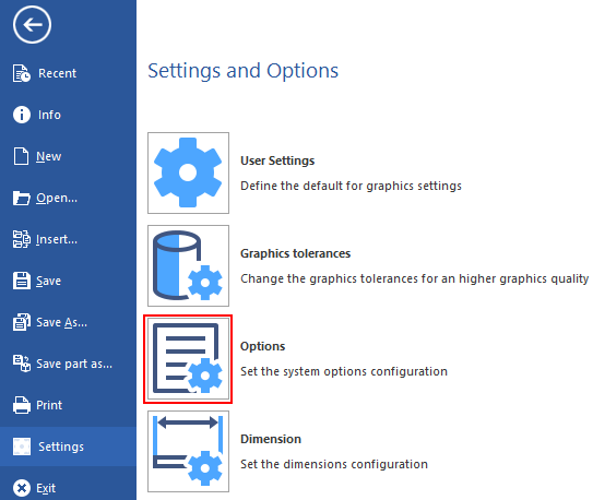
The system options configuration goes through the setting of several parameters available from the File > Settings > Options dialog. The values/settings defined here are considered as default and loaded at each new session.
Access
|
Click on File > Settings > Options icon. |
|
|
|
|
![]() Note: By clicking on the HUD button
Note: By clicking on the HUD button![]() it is possible to set some parameters also available in the System options dialog, as for example Grid and Graphics tolerances, but in this case the settings will be enabled only for the current session. Once you close the session, the default setting are reloaded.
it is possible to set some parameters also available in the System options dialog, as for example Grid and Graphics tolerances, but in this case the settings will be enabled only for the current session. Once you close the session, the default setting are reloaded.
The following options can be set:
- General
- File and Folder options
- User Interface
- Graphics
- Colours
- System
- Tolerances
- Graphics tolerances
- Drawing
- Grid
General
General options
|
VERO Home Page |
Link to the VERO Software website which can be set both here and from the System.CFG configuration file. |
|
Circle cross style name |
Allows you to set the style name for the axis of the circle. |
|
Units |
Allows you to set the measurement unit by choosing between millimetres and inches.
|
View options
|
View order for F2-F3 keys |
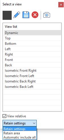
Allows you to set the order of the views when you toggle between them by using the function keys F2 and F3. Enter the numbers corresponding to the position of the views into the list displayed by the Select a view dialog (see below). |
|
View relative |
Activate this option to set the current workplane as default (instead of the absolute workplane) for toggling between views using the function keys F2 and F3. |
|
View change mode |
Allow you to define the view mode during the view changes:
|
![]() Note:
Note:
The View options can also be set for the current session only by toggling between the options View ABS and View REL from the Status bar. ![]() See illustration.
See illustration.

By clicking on the arrow on the right of View ABS (or View REL) you can load the Select a view dialog which allows you to:
- Select the required view from the View list, as for example Dynamic, Top and Bottom.
- Select the same View options described above: View relative and View change mode.
-
 Create new views based on one from the default list.
 -
 Save the new view.
 -
 Delete the new views. The system default views cannot be deleted.
 -
 Load the Snapshot Manager.
  See illustration.
Modelling options
|
Validate bodies on load |
Activate this option to verify the geometrical validity of each single solid both when opening the VDA file and during the modelling phase.
|
|
Check for corrupt solid data |
Activate this option to check for corrupted bodies from a mathematical point of view both when opening the VDA file and during the modelling phase. When a corrupted body is detected, a warning dialog displays.
|
|
Disable display of model tangent edges |
Activate this option to hide the tangent edges of the solids. Tangent edges are typically placed between a blend face and the adjacent ones (smooth edges).
|
File and Folder options
General options
|
Work Files Work files backup Global Symbols Plot Masks |
The system defines C:\Users\Username\Documents\FileName.VDF as the default path to store the following files:
However, if you save the files with the Save As... option in a different folder, the system will retain that as default for the subsequent saving.
|
|
Register file extensions |
Allows you to define the extension of the stored files. |
|
Backup interval (Mins.) 0=No backup |
Allows you to define the interval between two consecutive automatic backups of the current work file expressed in minutes.
|
|
Create a single restore file (restore.bak) |
If this option is selected, every time you save a work file the system creates a restore file named Restore.bak, also if multiple sessions of Designer are active and you work on multiple work files, in the User Profile folder. If the option is not selected, the system creates a restore file for any work file named FileName_restore.bak, in the corresponding work files backup folder.
|
|
Backup the work file on save |
Activate this option to create the backup of the current work file when saved. The backup file will be named as FileName_username.VDF.
|
|
Backup the work file on open |
Tag this check box to create the backup of the work file when loaded. The backup file will be named as FileName_original.bak and stored into the Work files backup folder.
|
|
Backup history |
Activate this option to create an incremental backup file every time a file is saved. For example, by saving the file FileName.VDF two times the backup files will be named FileName_001.VDF and FileName_002.VDF. The maximum number of back up files created can be defined by using the option Maximum history backup items described below. |
|
Maximum history backup items |
This parameter allows you to define the maximum number of backup files created when the Backup history option is selected. When the number is reached, the system continues with the progressive numbering but maintains the number of files specified by overwriting existing ones, starting from the oldest.
|
User Interface
General options
|
Max. No. of undoable entities |
Allows you to sets the number of Undo primitives on entities. When the value is reached a message prompts you to decide to continue or not with the Undo operation. As the Undo log occupies memory, the system gives you the opportunity to reset the log at the required interval. |
|
Use tabs on top |
Allows you to define the position of the tabs in the docked dialogue boxes. |
|
Show command prompts in graphics area |
Allows you to visualise the command prompts also in the top left side of the graphic area. If not checked the prompts will be displayed only on the bottom left side of the screen.
|
|
Use default font |
Allows you to set the default font size of menus and messages by choosing between:
|
|
Pick point default option |
Allows you to choose the default icon active in the point selection filters, when the pick point operation has to be applied:
|
Zoom options
|
Monitor width/height for real scale zoom (millimetres) |
Allows you to define the real scale (1:1) of the objects in the graphic area calculated in relation to the physical monitor dimensions rather than the Operating System (O.S.) internal values. |
Graphics
General options
|
Size of gravity field (Pixels) |
Allows you to set the size of the field around the cursor when searching points or elements. |
|
Maximum view depth (metres) |
Allows you to set the maximum depth of the graphic field. |
|
Marker dimension ratio (1.0=default) |
Allows you to enter the ratio to be used to calculate the size of some graphic markers, for example Origins and Points. For example, by entering the value 2, the Origins will be displayed at twice the size with respect to the default value (1.0). |
|
Slider dimension ratio (1.0=default) |
Allows you to enter the ratio to be used to calculate the size of the graphics sliders. For example, by entering the value 2, the sliders will be displayed at twice the size with respect to the default value (1.0). |
Shading options
|
Default body transparency (0.0-1.0) |
Allows you to set the level of transparency to be applied to each solid body created. The effect of the defined value is visible if the selected Rendering view is Shading or Shading with outline. The value must be between 0.0 and 1.0:
|
Drivers
|
Use hardware shading |
Allows you to select how the system has to manage the shading:
|
OpenGL options
|
Use VBO (recommended) |
Allows the use of virtual buffers to exchange the graphic data with the GPU of the graphic board. This option is valid for OpenGL only and could speed up the calculation process accordingly to the capability of the board. |
Colours
System Colours
|
Highlight colour |
Allows you to set the highlight colours by using the basic palette colour or the red, green and blue factors (RGB). Higher values will accentuate that particular hue. |
|
Dynamic selection colour |
Solids, faces and all the wireframe elements are highlighted when moving the cursor over them in selection and pre-selection phase. This option allows you to set the highlight colours of the dynamic selection mode by using the basic palette colour or the red, green and blue factors (RGB). |
|
Absolute origin colour |
Allows you to set the default colour of the absolute origin by using the basic palette colour or the red, green and blue factors (RGB). |
|
Open edge colour |
Allows you to set the default colour for the graphic display of open edges by using the palette colour. |
- Click on the box placed on the right side of the option that you need to customise.
- Select the required colour from the palette or define it by adjusting the RGB values. See illustration.
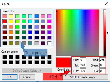
- If you need to have the defined colour in evidence for future use, click on the Add to Custom Colours to add it to the Custom colours section.
- Click the OK button.
System
|
Workplane size |
Allows you to set the default size of the visualised workplane. The value specified will affect the size of the shaded grey plane, which shows the workplane orientation. |
||||
|
Angle for circle pick points |
Allows you to set the angular position of the quadrant points placed on circles. These points are automatically searched and highlighted when you move the mouse over a circle and the Quadrant of a circle icon |
||||
|
No. decimal digits in sketching |
Allows you to set the number of decimal points shown when making sketch operations.
|
||||
|
No. decimal digits in query |
Allows you to set the number of decimal points shown in the option dialog displayed when a Query command is loaded from the Analysis > Query tab. |
||||
|
Dynamic snap |
Allows you to set the distance between two consecutive cursor positions during sketch or freehand positioning. |
||||
|
Dynamic step value |
Allows you to define the value of the step that scrolls in the dynamic input fields using the mouse wheel or the spin buttons. |
||||
|
Dynamic angular step value |
Allows you to define the value of the angular step that scrolls in the dynamic input fields. |
Tolerances
|
Quick profile/hatch tolerance |
Allows you to define the maximum value of the tolerance to fill gaps between elements when creating a profile. This value can be adjusted during the profile creation using the Tolerance |
|
Chordal tol. for data conversion |
Allows you to define the maximum value of the chordal tolerance accepted during data conversion. |
|
Angular tol. for data conversion |
Allows you to define the maximum value of the angular tolerance to be applied during data conversion. |
|
Max radius for data conversion |
Allows you to specify the maximum radius admitted in data conversion. For example, when a curve/polyline is converted into arcs/segments, this value will represent the maximum radius to be used for the computed arcs. |
|
Tangent edges default angular deviation |
This parameter defines the default value of the angular deviation of the tangent edge during:
|
|
Default mesh tolerance |
Allows you to define the mesh tolerance value according to the source and nature of the data and application.
|
|
Volume calculation accuracy |
Allows you to define the accuracy level (from Low to High) of the volume calculation for the selected solid. The value of the Volume can be displayed by using the command Analysis > Weight |
Graphics tolerances
Wireframe tolerances
|
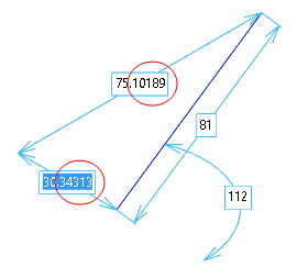
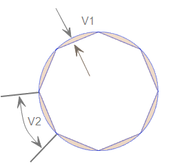
Max. chordal error & Max. angular error |
Allows you to set the maximum tolerance values for displaying circles and arcs as a series of straight-line segments. The smaller the value, the larger the number of segments generated for a particular arc and the closer is its appearance to a circle.
V1 = Chordal error V2 = Angular error
|
Shading tolerances
|
Shading quality |
Allows you to define the shading quality by positioning a scrolling bar between the values Min and Max. |
|
Use mesh tolerances |
Allows you to activate the mesh tolerances. |
|
Mesh chordal tolerance |
Allows you to set the chordal tolerance the system has to use during mesh operations. |
|
Mesh angular tolerance |
Allows you to set the angular tolerance the system has to use during mesh operations. |
Drawing
|
Allows you to define the size of the circle cross as a percentage of the circle's radius. |
|
|
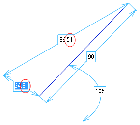
Arrow length in sketch Arrow angle in sketch |
Allows you to define the arrow size during the sketch commands by specifying:
|
|
U radial hatch angle Radial hatch distance V radial hatch angle |
These parameters allow you to define the position of the intermediate curves shown on:
In detail:
|
|
V parametric hatch (0-1) U parametric hatch (0-1) |
These parameters allow you to define the position of intermediate curves during the definition of surface or solid face shapes. You have to enter decimal values between 0 and 1. For example
|
|
Zig-Zag style angle Zig-Zag style length |
Allows you to set the characteristics of the zig-zag style line by specifying its:
|
|
Irregular style angle Irregular style length |
Allows you to set the characteristics of the irregular style line by specifying its:
|
Grid
![]() Note: The parameters described below can also be set by selecting the Grid > Grid parameters, Grid > Show/Hide grid, Grid > Enable/Disable grid snap options from the burger
Note: The parameters described below can also be set by selecting the Grid > Grid parameters, Grid > Show/Hide grid, Grid > Enable/Disable grid snap options from the burger ![]() icon. In this case they are immediately applied but are limited to the current session. When defined in the System options dialog, it is necessary to restart the system for them to be set as default value applied each time a new session is started.
icon. In this case they are immediately applied but are limited to the current session. When defined in the System options dialog, it is necessary to restart the system for them to be set as default value applied each time a new session is started.
|
Grid size |
Allows you to define the main width and height dimensions of the grid displayed on the screen when the Show grid check box (see below) is selected. |
|
Vertical grid pitch Horizontal grid pitch |
These parameters allow you to set the characteristics of the internal part of the grid by defining the vertical and horizontal grid increment. It can be considered as the distance between the grid elements along Y and X axes. |
|
Horizontal snap Vertical snap |
These parameters allow you to specify the horizontal and vertical snap increment between grid elements. |
|
Bold step |
This parameter defines the number of grid elements between two consecutive bold elements on the grid. For example, if the value is 5, the system draws a bold element every 5 elements. |
|
Angular snap |
This parameter allows you to define the value of the angular snap on the grid, and it is used for the Single Element dimension on circles and for Text Leader dimensions. |
|
Show grid Enable snap Enable angular snap |
When activated these parameters allow you to:
|
|
Grid style |
This parameter defines the style to be used to draw the grid on the screen. The style can be chosen from the following:
|
|
Grid Colour (r,g,b) |
This parameter allows you to specify the colour of the grid by using the colour palette or by adjusting the r, g, b values. Click here to see details. |
![]() Note: Some changes may not be implemented until the application is restarted.
Note: Some changes may not be implemented until the application is restarted.
A message to this effect is displayed in the bottom right corner to alert users.